This page logs my setup and ongoing experimentation for development
of 'Internet of Things', specifically using the Raspberry Pi,
to carry out a "Tuya Conversion" for smart electrical switches.
.
The specific requirement is to convert the 'Deta Inline Switches' so that they than
can be controlled without connecting to 'Grid Connect' or 'Tuya' cloud services.
They can then controlled locally from 'Home Assistant' without needing a working NBN connection.
.
Deta Inline Switch:

.
These switches are available from electrical supply wholesalers, and from Bunnings
Deta Grid Connect Smart Inline Switch
[currently $23.96 from Bunnings].
It says ... Rated at 250V AC 50Hz 10A with Australian and New Zealand standards approvedl.
and ... "This product must be installed by a licensed electrician or qualified person".
All testing is being carried out using the switch in desk lamp cable, and final installation will be done by an electrician .
Most of this web page details the procedure copied from
Tuya Convert 2.3 Flash Tuya Smartlife Devices
[by digiblurDIY]
I would recommend watching the video before you start.
The details discussed in this video are contained on
Details Tuya Convert 2.3 Flash Tuya Smartlife Devices
[by digiblurDIY]
.
Step1: Setting up a new Raspberry Pi 3:
This section describes the steps in setting up a new Raspberry PI.
- Go to the Raspberry PI OS download page at Raspberry PI OS (currently Ver 5.10)
- Download "Raspberry Pi OS Lite" ZIP file.
- .... Note where the File ( eg: "2021-03-04-raspios-buster-armhf-lite.zip") is downloaded to
- .... - usually the 'Downloads' directory - leave it 'zipped' for now.
- Insert and Format your microSD card to FAT32
- Download the image writer program 'Etcher' from Etcher
- .... - (Ensure it is correct Version for your 'Operating System' )
- Choose 'Save File'.
- .... Locate where this File is downloaded to (usually 'Downloads' directory)
- Create a working directory (eg. "G:\RaspberryPi3-Tuya-Convert") and drag both files there.
- Double click the 'Etcher-Setup-xxx' application - it will install and run immediately.
- In the 'Etcher' box click 'Select image' - choose eg. "2020-02-13-raspbian-buster-full.img"
- In the 'Etcher' box (check SD drive info) and click 'Flash'.
- ... wait for it to complete 'flashing', and complete the 100% verify.
- ...
- Unplug the microSD card adapter, wait a few seconds and plug in again
- You will now see a new drive called 'boot'
- Create a new blank file and name it name 'ssh.txt'
- Delete the ".txt" extension and confirm that you want to remove the extension anyhow.
- You should now have a file in the disk named "ssh"
- Eject the microSD card
- ...
- ...
- ...
Step2: Configure the new Raspberry Pi 3:
'Insert' Raspberry PI OS microSD card...
- Power up, and wait for boot-up completion...
- Identify the IP address, and log in though Putty. [User: 'pi', and password 'raspberry']
- We now have configure to the basic Raspberry Pi..
- ...
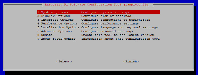
- sudo raspi-config
- ...
- First we must update this actual software - click on '8, Update' and wait for the menu to open again.
- ...
- If you want extra security then Change the password,
---- Usually not required as this only a temporary system
- ...
- Then you should expand the available storage,
- Select '6, Advanced Options'
- Select 'A1,Expand Filesystem'
- You will get the message "Root partition has been resized.
--- The filesystem will be enlarged upon the next reboot OK"
- ...
--------- Raspi-config Main Menu:
.
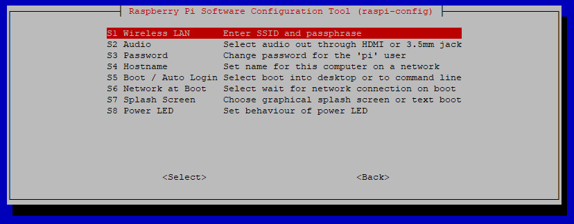
Set up the WiFi region
- It important to set up the WiFi country code,as it
sets the frequency bands that apply in your area...
- ...
- -- but do not enter your wifi SSID and Password at this
time - just hit 'ESC' when the questions are asked.
- ...
|
|
|
.
Select your region for the Wifi:
...

|
Select your country from the list:
- Use the Up and Down arrows to move
-
- In this example I have selected Australia.
-
- Select your Country then tab to OK
-
- Press 'Enter' and it will ask for your SSID.
-
- You must press 'ESC' (Cancel) at this time.
|
|
- ...
- Select 'Finish' and agree to the 'Reboot' suggestion. ...
- If not asked do enter this:
-
- sudo reboot
-
- ...
- The Ptty window will close - wait about 30 seconds and then reopen the window...
-
- Log in to the Raspberry Pi. [User: 'pi', and password 'raspberry']
- Enter the following commands, and wait for each one to complete
- [Copy each command from this page and 'Right Click' the mouse button in Putty (then 'Enter' key).]
-
- sudo apt update
-
- sudo apt install git
- ---
- git clone https://github.com/ct-Open-Source/tuya-convert
- ---
- cd tuya-convert
- ---
- ./install_prereq.sh
- ---
- sudo reboot
- ---
- Wait 30 seconds, --- then from Top level menu select 'Restart Service' and log in again.
- ---
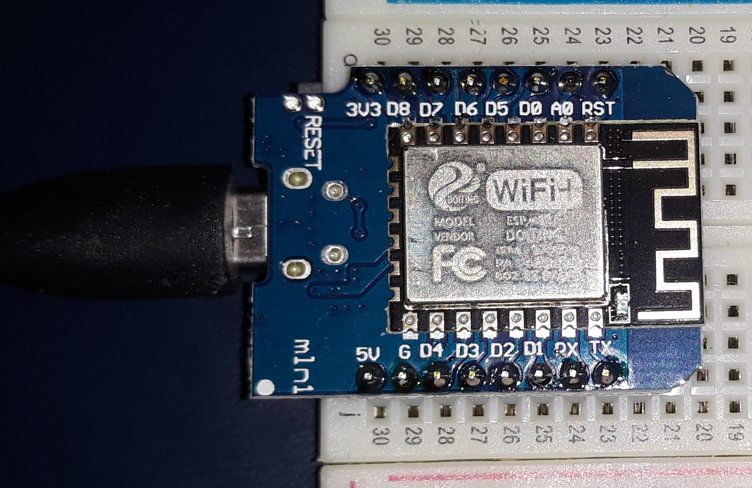
Step3: Prepare the Wemos (D1 Mini NodeMCU) as Donor device
- The NodeMCU is programmed as a substitute device for a smartphone attempting to connect to "vtrust-flash"
- ---
.'tuya_convert_donor_01'
.
- Make sure the NodeMCU is still flashing regularly'
- ---
- cd tuya-convert
- ---
- ---
- The newly configured device is usually set to '192.168.4.1'
- ---
Set the Deta Switch into 'Pairing Mode'...
- Put your Deta Switch in autoconfig/smartconfig/pairing
mode (the blue LED will blink fast).
- ...
- Make sure nothing else is plugged into your IoT device
while attempting to flash.
- ...
- For the Deta 6000H device you must switch the power on
and off three times - leaving it on after the third switch.
- ...
- The blue LED will then start flashing rapidly
- indicating 'pairing mode'.
- ...
|

|
|
- ---
- If there is too long a delay after you first set it, then the Tuya Conversion process may may fail, and
'mess up' the device. Such 'bricked' devices need to be fixed by opening it up,soldering wires to
to the board, and direct electrical programming. Very difficult and not at all recommended.
- ---
- If you have to 'pause' just turn the power off --- and when prompted by 'Tuya Convert' then set up pairing again.
- You may need to press the 'reset' button when you turn it on again --- before starting the pairing again.
- ---
- Once both the IOT device and the NodeMCU are flashing you can enter the command on the Raspberry Pi...
- -
- ./start_flash.sh
- -
- The 'Tuya Convert' program will then print a strong warming message.
- When you are asked for confirmation you must type 'yes' (spelled in full) and hit 'Enter key'
- ---
- The program has to free up several ports to do the search. (eg: dnsmasq, and mosquitto)
- Type 'y' to 'terminate' these programs.
- ---
.
- The following test image shows a Successful run of the Tuya Convert Program.
- -
- Make sure both devices are flashing, and when asked to press ENTER to continue - do it!
- -
- When asked to select firmware - Choose "2) flash tasmota.bin"
- -
- and answer 'n' when asked "Do you want to flash another device? [y/N]"
- ---
- At this time you need to activate a wifi module on your windows 10 PC
- I had to purchase a small add on module because my PC did not have Wifi Capability.---
- ---
This is the New Tasmota device
- ---
- Usually the '192.168.4.x' network is only
accessible on a "Tamotaxxx' SSID wifi network
- To find this device I turn on a different wifi
interface and look for the "Tasmotaxxx' SSID
- Open a browser at that address ---
- ---
- This is the Tasmota 'Server' on '192.168.4.1'...
- -'
- ...
|

|
|
- ---
Connect to he Tasmota_xxxxxx_xxx WiFi Server:
...

|
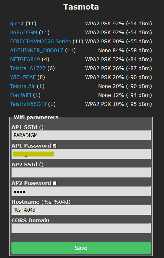
Select your WiFi network from List (eg: PARADIGM):
- Click on that network and the SSID is filled into the first box.
-
- In the second Box fill in the Password for that network.
- Tick the small box above the entry to show that you have spelled it correcty
- Ensure that the password is correct - You will not be able to find the device if wrong
-
- Click on "SAVE" and the page connection will be lost.
-
|
|
.
- ---
- ---
- ---
- ---
- The newly configured device is usually set to '192.168.4.1'
This is the Tasmota 'Server' found at the default address 'htpp://192.168.4.1'
- ---
- Usually the '192.168.4.x' network is only
accessible on a "Tamotaxxx' SSID wifi network
- To find this device I turn on a different wifi
interface and look for the "Tasmotaxxx' SSID
- Open a browser at that address ---
- ---
- This is the Tasmota 'Server' on '192.168.4.1'...
- -'
- ...
|

|
|
- ---
.
Select Your WiFi Network:
...
|
Select your WiFi network from List (eg: PARADIGM):
- Click on that network and the SSID is filled into the first box.
-
- In the second Box fill in the Password for that network.
- Tick the small box above the entry to show that you have spelled it correcty
- Ensure that the password is correct - You will not be able to find the device if wrong
-
- Click on "SAVE" and the page connection will be lost.
-
|
|
.
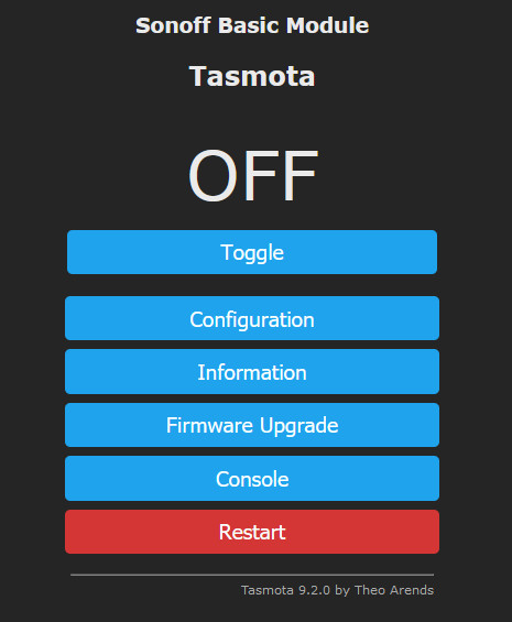
This is the Tasmota Basic Server on the 'PARADIGM' NETWORK
- The address has to be located within the PARADIGM wifi network
- ...
- You can scan using "Advanced IP Scanner"
- Or by viewing your 'Router' list sorted by 'Uptime' ...
- ...
- In this case it was seen on '192.168.1.171'
--- as "tasmota_357BDE-7134.localadmin"
- ...
- Opening a browser at that address gives this display.
- ...
|
|
|
- ---
The Upgrade defaults to "http://ota.tasmota.com/tasmota/release/tasmota.bin.gz"
If we Upgrade to the 'Full Size Tasmota, any attempt to add new programs will fail
due to the maximum size of 1MByte Flash size.
- ---
- Clicking on Information gives this display [with your own information]-
------ Tasmota -> Information:

.
- ---
.
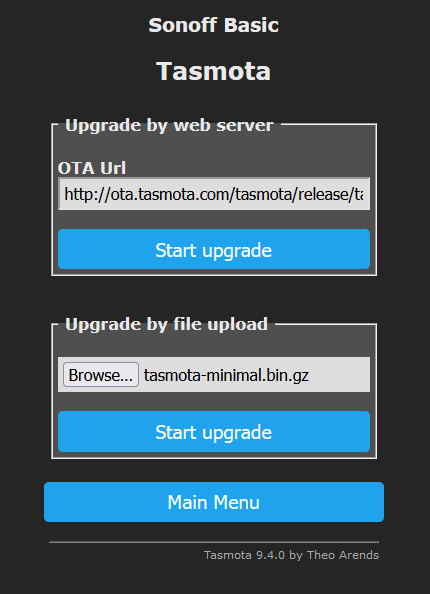
Upgrade The Firmware:
...
|
Upgrade The Firmware::
- Download the tasmota-minimal.bin.gz.
-
- In the second 'Browse' and find the file in your download directory.
- Click on the lower 'Start Upgrade'
-
-
|
|
.
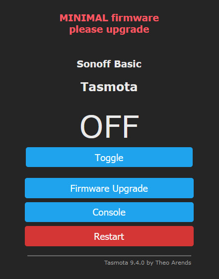
This is the new Minimal Tasmota Basic Server.
- The reason for downloading and Upgrading to the Minimal Tasmota..
- is to ensure that new firmware can be loaded 'Over The Air'...
- without exceding the 1 MByte Flash Memory size.
- ...
|
|
|
- ---
.
.
.
-
"Deta Switch 170 - NodeMCU (Wemos) Test Bed":

-
.
.
.
.
.
.
EXPLANATION ABOUT HTTP-REST AND MQTT CONTROL:
IMPORTANT NOTE:
All he following examples use the older 'naming conventions'.
Recent changes now require the use of 'Hyphens' in place of 'Underscores'
The default for control devices under ESPHome is to use REST
- REST web services are just web services that follow a 'RESTful' architecture.
- HTTP is a contract, a communication protocol and REST is a concept.
- REST implies a series of constraints about how Server and Client should interact.
-
see this article for "A Beginner’s Guide to
HTTP and REST
-
-
-
- This initial Yaml File supports controls (Switch and Led) through HTTP-REST
- With this Yaml file the two Entities can be found and added to a lovelace card.
-
Home Assistant Lovelace Card for "Deta Switch (NodeMCU) 170":

-
- Examining the MQTT Messages using MQTT spy shows...
-
MQTT messages from "Deta 172":

-
- As a quick test I also added one MQTT message at the bottom or the file
- It sends a MQTT message "topic: esp_switch_172/starting"
- and include the "payload: online"
-
- This MQTT message can be observed using MqqtSpy.
-
- After several starts I have observed ON/OFF mqtt messages for LED and relay
- Apparently this is a feature of the setting "discovery: True"
-
- See this reference MQTT Discovery
-
- From the left side-bar select "Configuration" then from list on the right "Devices".
- Find "esp_switch_172" under "MQTT" in the list and click on it.
\
- Under "Device Info" click on "MQTT INFO"
- This will display the MQTT configuration details page.
- At the top of that page we see two switches.[Both are enabled]..
- Payload display
- ...[<=0>] Attempt to parse MQTT messages as JSON
- ...[<=0>] Show as YAML
- Entities.. (as shown)
-
-
Home Assistant Lovelace Card for "Deta 172":

-
.
- ---
Setup the your "esp_switch_172.yaml [Using MQTT Messages]"
- Go to "ESPHome" in the sidebar
-
-
-
- Click on the Green (+) at the bottom right to create your first device
- Enter the name 'esp_switch_172'
- Select 'Generic ESP8266 (for example Sonoff)'
- This can be changed to 'board: esp01' or some other value when the "esp_switch_172.yaml" file is updated
-
- Once Installed the 'yaml' file may appear empty. Select 'Overview' and then return to 'ESPHome'
- Click on Edit and overwrite any text in the editor window with the following text.
-
.'esp_switch_172.yaml'
.
There are the links explaining how to create YAML file in ESPhome and upload it to Tasmota device.
- Migrating from Sonoff Tasmota — ESPHome Overview
- Using With Sonoff Basic — ESPHome Details
- ---
- Now you have to log into the 192.168.1.171
- Upgrade the Firmware to Minimal, but don't do the full size version.
-
- See:===> https://github.com/arendst/Tasmota/releases
- Then go to -> http://ota.tasmota.com/tasmota/release/ and download tasmota-minimal.bin.gz
- Find "tasmota-minimal.bin.gz" and in the Tasmota window select update Firmware from file
-
- Unfortunately you only get to do this once!!!
- However ESPHome 'Over The Air Update' apparently works for very small changes
- The Firmware appears to work correctly switches operate the LED and Relay, and button sets the status correctly.
-
-
-
|
STEP 4: Create New ESP Switch Device - Using Recent Changes to ESPHome naming rules.
-
-
- In late June 2021 ESPHome made major changes to the way way Devices and Entities are named.
- There are the links explaining the recent changes
- The main impact was they no longer supported the use of the 'Underscore' character in entity names.
- The later version automatically converts all 'underscores' to 'hyphens'
-
- Apparently this was done to enable the 'entity names' to be used in 'http' addresses to for 'REST' operation.
- Soon after the changes Home Assistant was unable to automatically detect these 'hyphenated' names.
-
- Home Assistant still operates anyhow with 'Underscore' names that were previously created.
-
- For the next Deta Switch it was decided to just leave out the hyphens/Underscores and merge the words together.
- 'esp_switch_104' will become 'espswitch104'
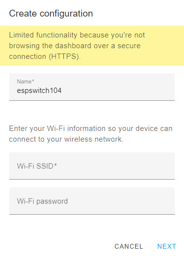
Setup the your "espswitch104.yaml device
- ..
- Go to "ESPHome" in the sidebar
-
- Click on the Green (+) at the bottom right to create your new device
-
- Enter the name 'espswitch104'
- ..
- Then enter your Wifi Network SSID (in the Wi-Fi SSID* field)
- ...
- And then enter your 'Password' for that network
- ...
- The network SSID and Password will be replaced with the 'secret' entries
later when we paste in the yaml text file.
|
Creating a New ESP Device.
|
|
-
- Locate the 'espswitch104' box and click on 'Edit' and overwrite any text in the editor window with the following text.
-
.'espswitch104.yaml'
- The following options are displayed in the bottom right corner of the Editor Window
-

-
- After you have pasted the above text into the window click on "SAVE"
-
-
- After you have pasted the above text into the window click on "SAVE"
-
- Then click on "CLOSE"
-
- On the EspHome page go to "espswitch104" and click on "VALIDATE"
- The following options are displayed in the bottom right corner of the Validate Window
-
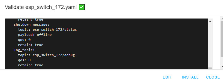
-
- Then click on "Install"
- In the following Dialog box select 'Manual download'
- When the compilation is complete - click on 'DOWNLOAD BINARY'
- Down the bottom of the window you will see the download 'espswitch104' box indicated.
- In the pop up Dialog box select 'Show in Folder'
- Drag it to 'D:\Downloads' - or some other location that is easy to remember
-
- ESPHome 'Install' dialogue box

-
-
- Apply power to your 'Tuya Converted' Deta Switch that
- has been updated to 'Tasmota Minimal' configuration.
-
- Open a new browser window and type in the address http://192.168.1.104/
- Click on 'Browse' in the 'Upgrade by file upload' field and choose the file 'espswitch104.bin'
-
- Tasmota-Minimal-Firmware - Upgrade Menu
-

-
- Click on the 'Start Upgrade' button just under the file name.
-
- Wait for the the confirmation of the upload, and the Tasmota menu will become inactive.
-
- Because the Yaml file specified that Home Assistance should be updated,
you should now be able to find the specified 'Entities'
-
- These entities are:
- detaswitch104
- detaled104
- detabutton104
-
- In Home Assistant go to the left side panel and click on 'Overview'
- Then click on the 'three dots' in the top right corner and select 'Edit Dashboard'
- Now click on the blue button in the bottom right corner 'ADD CARD'
-
- In the new dialog box click on the top tab 'BY ENTITY'
- In the 'search entities' field type in 'detaswitch' and the 'detaswitch104' will appear in the list
-
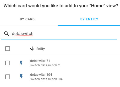
-
- Click on the box in front of that entry, and then 'CONTINUE'
-

-
- Click on the 'ADD TO LOVELACE UI'
-
- Now find that new card in the overview and click on 'Edit' which will bring up the 'Entities CardConfiguration'
-

-
-
- You can now add a Title, and add the next two entities to that card
- When finished click on 'CLOSE'
-

-
-
- Create a Snapshot "After New espswitch104 installed"
-
There are the links explaining how to create YAML file in ESPhome and upload it to Tasmota device.
.
The following page explains how to develop a PIR (Passive Infrared) Sensor.
- IOT SETUP - PIR SENSOR
(Includes PIR test-jig)
.
OPTIONAL - RASPBERRY PI - SET A FIXED IP ADDRESS
[ Unlikely to be required ]:
Setting A Fixed IP Address for Raspberry Pi...
- In the PuTTY command window get the current configuration
- sudo ifconfig
- Note "eth0" specifically
- Must set up interface eth0: in config file.
- inet addr:192.168.1.20 Bcast:192.168.1.255 Mask:255.255.255.0
... see this article for Jessie...
Refer to Setting Static IP
-
- sudo nano /etc/dhcpcd.conf
... Go to the end of the file and add these lines...
... This presumes and Address of 192.168.1.21 (change to preferred values)...
... To copy a line in 'Nano' first 'Cut' (Ctrl+K) and 'Uncut' (Ctrl+U) twice...
-
-
To exit the editor, press ctrl+x
To save your changes press the letter “Y” then hit enter
- Shut down Raspberry Pi ('sudo shutdown -h now') and power off and on to Restart
- Don't forget you need to change your PuTTY address to new IP
|
.
Last updated: 07-AUG-2021 at 10:37 PM.
|
|