IOT SETUP - PIR SENSOR

This page logs my setup and ongoing experimentation for development of 'Internet of Things',

Specifically it describes the design and setup of a 'PIR' (Passive Infra-Red) Sensor module
and its setup in Home Assistant.

.

For more information on PIR Modules see 'Passive Infrared Sensor' ... from ESPHome
Note that the device needs a 5-12 Volt supply and the ouput is 3.3 Volt logic level.


------ PIR Sensor Front View [from ESPHome]:

PIR-Front-View-ESP-Home-001


  • ------ PIR Sensor Circuit board [from ESPHome]:

    PIR-Board-ESP-Home-001

  • Using the Wemos (D1 Mini NodeMCU)

    • The NodeMCU is programmed to detect PIR motion and generate MQTT messages
      • The PIR sensor will be managed by a NodeMCU wifi module
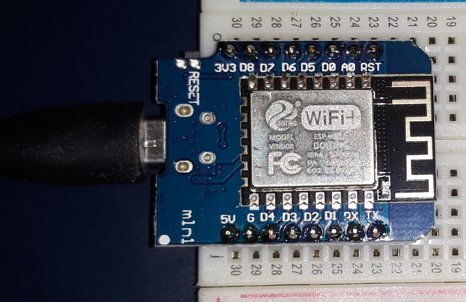
        The chosen module is the 'Wemos D1 Mini'.
        This module provides a simple clean interface and is easily programmed 'Over the Air'.

        .

        ------ Wemos D1 Mini NodeMCU:

        D1 Mini NodeMCU

      • To test the behavior of the PIR a Test-Bed was constructed to experiment with the PIR settings.
      • .

        "PIR Circuit - NodeMCU (Wemos) Test Bed":

        Wemos-NodeMCU-PIR-010_bb.jpg

        .

        .

        .

        "PIR Circuit - NodeMCU (Wemos) Schematic Test Bed":

        Wemos-NodeMCU-PIR-010_schem

        .

        .

    • The above Fritzing diagrams show how the NodeMCU and the PIR are wired up.
    • As an initial setting adjust the 'Sensitivity' to half way, and the 'ReTrigger Time' to fully anti-clockwise.
    • Now we have to program the NodeMCU to run the test program.
    • Run the Arduino IDE and open a new 'Sketch' which contains some suggested code.
    • Select and Copy the all text from the following window.
    • Paste all the text (overwriting the new 'Sketch' suggestions).
    • 'File => Save As' the Sketch 'NodeMCU-PIR-Test-01' .
    • Ensure that the 'Tools => Board:' is set to 'Generic ESP8266 Module'
    • and the board is selected as 'Node MCU' to ensure the correct names for pins
    • 'Verify / Compile' the Sketch.
    • Connect the NodeMCU to a USB port,
    • Click on 'Tools => Port' and note the Port number is correct
    • Click on 'Tools => Serial Monitor' which will open a window showing all the serial comms
    • Down the bottom of that window ensure the speed is set to '9600 baud'
    • 'Upload' the Sketch.
    • The Green 'Clock Tick' LED will start flashing (about 5 times per second)
    • When movement is detected by the PIR the Yellow 'PIR Detected' LED will light up.
    • ---

    • 'NodeMCU-PIR-Test-01'

      .

      • ---
      • Slowly adjust the 'Sensitivity' Potentiometer screw until the optimum PIR Sensitivity is set.

      Creating the Actual PIR Sensor

    • A suitable box and installation must now be designed.
    • Designing a layout of the actual 'PIR module' so that the adjustment screw can be accessed
    • requires the 'PIR module' to be near the bottom of the box to prevent water access.
    • Jaycar has a range of small boxes that are perfect. Outside mounting holes and reasonable sealing.
    • Snap Fit ABS Enclosure 82 x 82 x 44mm Jaycar About $6.95
    • Jiffy Box - Black with mounting flange - 83X54X31 - UB5 Jaycar Approx $3.75
    • Bulkhead - Black - 88 x 69 x 33mm Jaycar About $4.75

    • ------JAYCAR Snap Fit ABS Enclosure 'HB6008':

      Jaycar-ABS-Enclosure-HB6008--01


    • It may be possible to use one of the smaller cases
      - but I have chosen the larger 'HB6008' for easier fitting.
    • This box mist be mounted with the flanges on both sides,
      and the Veroboard across the top edge.
    • The PIR module is mounted on the bottom edge over against
      the Right Hand Side.
    • The Sensitivity adjustment screw is accessed through a small
      hole drilled in the lower edge.
    • .

      "Actual PIR Circuit - NodeMCU (Wemos) Veroboard design":

      Wemos-NodeMCU-PIR-28x14-Veroboard-044_bb

      .

      .

      .

      "Actual PIR Circuit - NodeMCU (Wemos) Veroboard Circuit Schematic":

      Wemos-NodeMCU-PIR-28x14-Veroboard-044_schem

      .

      .

    • .

      ------ The Fritzing template for the Veroboard (bottom view):

      veroboard-14x28-Fritzing-001

    • The correct size for the Jaycar 'HB6008' case is 28 columns by 14 rows.
    • Cut the Verobaoard to that size along the next adjacent row of holes
    • .

      ------ The Actual Verobord after tracks have been cut:

      veroboard-14x28-Actual-no-drills-004.jpg

    • These Tracks were cut with a 1.2mm ball engaving bit. Better results would have been obtained with a 0.8mm bit.
    • .

      ------ The Top View of the Verobord showing which holes have to drilled through into the box.

      veroboard-14x28-Actual-Top-View-Drill-004.jpg

    • Remember the actual Veroboard is flipped over - so the copper tracks would be underneath.
    • The three larger holes are for mounting, and the small holes are for mounting the LEDs.
    • I would suggest doing the large holes first and then use screws to hold the board in
      place while the smaller holes are drilled.
    • These are two small holes for each of the three LEDs which are later expanded to allow the
      LEDs' to poke through the box.
    • [Take the Veroboard out and drill a small hole between each pair to use as a pilot hole for the LED.]
    • The PIR Module requires a 22mm hole to be drilled through the case for mounting the 'PIR Module;
    • The Template as shown here is available for download as a pdf file.

    • Template for ESP PIR Sensor Box-vero-scews-011.pdf -To download Right Click and 'Save File As'
    • You may need the 'Adobe" to print this page - you must select 'Actual Size' (not 'Fit to Page') .
    • It can then be printed - and will be actual size - which can be cut out and placed in the box.
    • The 'hole' positions can then be marked with a centre punch and drilled when the template is removed.


    • Template-ESP-PIR-Sensor-Box-001.jpg

    • .

      .

      Last updated: 06-SEP-2021 at 1:04 PM.
    ©2004-2014 Paradigm Electronics
    Home | About Paradigm Electronics | Products & Services | Contact us | Site map | Useful Links | Client | ANMF test | Android | Ham Data | Logout |